Nxt Line Follower Program Follow Black Line
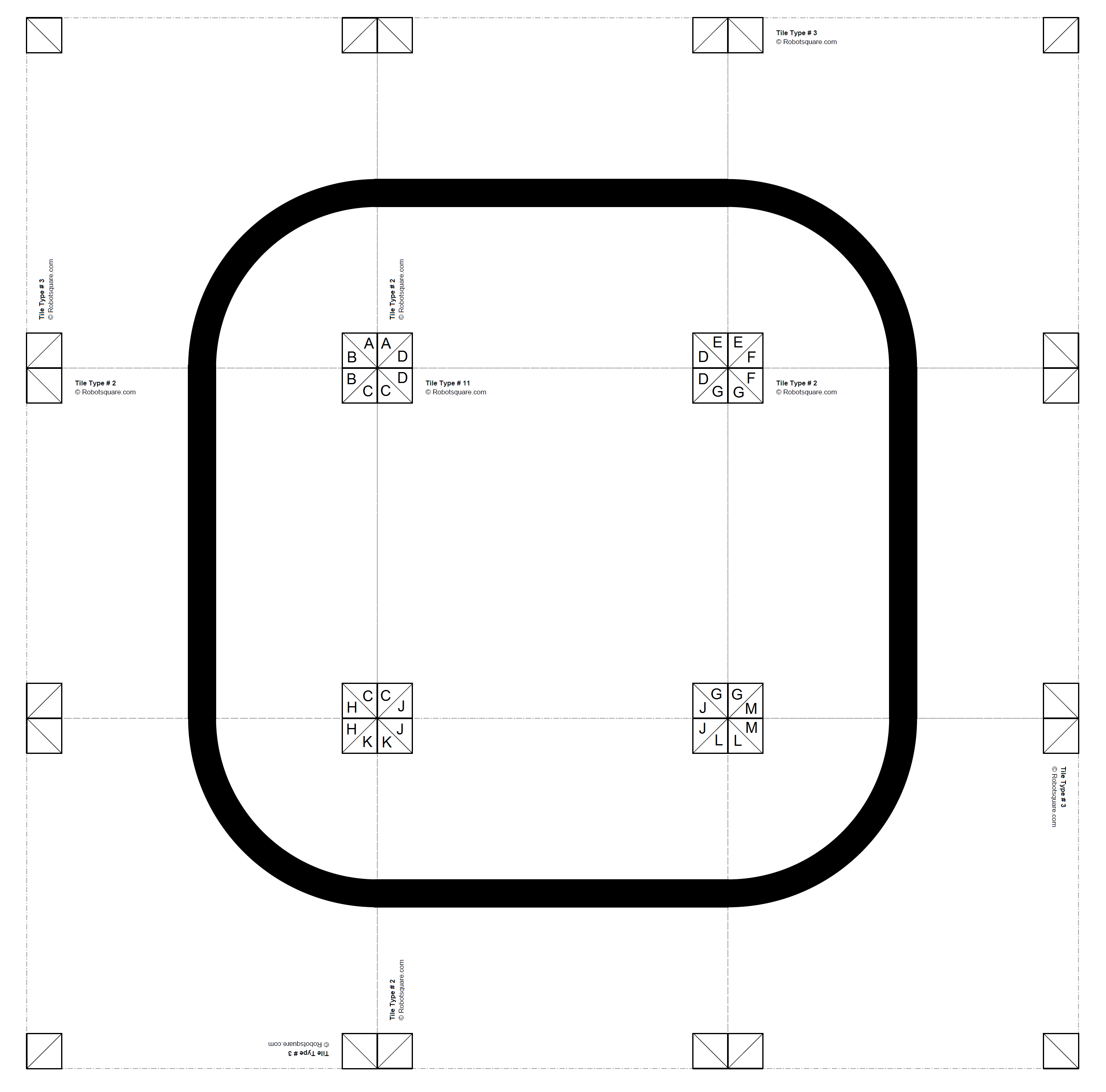
Tags: ev3 line follower ev3 pid controller line following code line following tutorial. If you happen to have the Mindstorms NXT 2.0 it has a mat with a big elipse-like line that works great for this tasks. Let’s see again the pseudo-code. Program LINE FOLLOWING. White = 0, black = 0.
1998 world cup song download. Line follower program for nxt robot lego mindstorms Following these documents, I was able to implement a PID controller to enhance the performance of a line-following robot. Therefore, when I first watched video clips of a self-balancing Segway-type robot and a robot that could balance itself on a ballI was fascinated by the applications of control theories and sought to learn more. I have devoted myself to robot education since I was a freshman. The original version by Lego uses the reflected light to distinguish between black the line and white the floor. The motor power itself as well is a value between 0 and To produce the motor commands as described in the schema, the following calculations have to be done. This was the result of the robot following a straight black line and the initial position of the light sensor targeting the black area.

After I became familiar with the theory, I also used it to solve other problems, such as precise turning of the robot, when I was preparing for the field robot competition. The error indicates how far the robot is from the edge of the black line; when the light sensor of the robot remains near the edge of the black line, the error is close to zero. When the sensor is on line follower program for nxt robot lego mindstorms white surface, the right motor is activated and the robot turns left.
Original Line Follower Courtesy of Davidin2. As a result, I successfully implemented PID controller to enhance the performance of a line-following robot: The more the sensor gets on the line, the blacker the perceived colour is. The approach is very simple and effective. A typical value for a black surface is around 20 and for a white surface something around The program interface is illustrated in Fig. In the following, an improved version, based on Fuzzy-Logic, is presented. The error indicates how far the robot is from the edge of the black line; when the light sensor of the robot remains near the edge of the black line, the error is close to zero.
In this way, if exactly on the colour boundary, the robot runs straight ahead. On the other hand, the more the sensor gets on the white surface, the whiter the perceived colour is. After I became familiar with the theory, I also used it to solve other problems, such as precise turning of the robot, when I was preparing for the field robot competition. 
As can be observed in Fig. Fortunately, well-written tutorials are available on the Internet. As a result, I successfully implemented PID controller to enhance the performance of a line-following robot: A typical value for a black surface is around 20 and for a white surface something around When the sensor is on the white surface, the right motor is activated and the robot turns left. I have devoted myself to robot education since I was a freshman. As a result, I successfully implemented PID controller to enhance the performance of a line-following robot: The idea behind the new version is, not only to distinguish between black and white, but to consider various degrees of grey.
Following these documents, I was able to implement a PID controller to enhance the performance of a line-following robot. This was the result of the robot following a straight black line and the initial position of the light sensor targeting the black area. When the sensor is on the white surface, the right motor is activated and the robot turns left. These values depend of on the ambient right conditions and the distance of the sensor from the surface. The recorded data, which is the error versus time, will be displayed on the graph.
